 Go to the
SiliconValley GeoCities

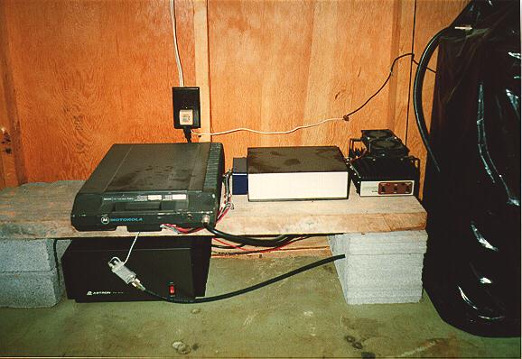
The antenna adapter is in the receive line between the
Duplexer
and the
Transceiver
to adapt the PL-259 connector to a phono type jack.This particular adapter is simply a surplus, low loss antenna switching relay.
Back to Image
Back to Repeater Page
The power supply is an Astron RS-50A, 13.8 Volts@50 Amps. The repeater draws less than 15 Amps of current while transmitting so the 50 Amp supply provides plenty of current overhead.
Back to Image
Back to Repeater Page
The transceiver is a standard Motorola Micor® which has been modified for repeater use. The repeater modification allows the transceiver to transmit and receive simultaneously. The transceiver does not have a receive pre-amp installed, however, the receiver sensitivity is still less than .25 uV@20dB quieting. The power out of the transceiver has been lowered to between 1 and 2 Watts to drive the external
Power Amplifier
. A spare transceiver is available to allow quick replacement in the event of a failure.
Back to Image
Back to Repeater Page
The control head is basically the volume and squelch controls in a project box. After modifying the
Transceiver
for repeater operation, most of the functions of a factory control head are not needed, so a simpler version was fabricated to allow adjustment of the volume and squelch externally.
Back to Image
Back to Repeater Page
The repeater controller is an ACC RC-85 microprocessor controller housed in an aluminum case. The single board provides all of the repeater functions, timers, phone patch, etc. All of the inputs and outputs are connected through a single 25 pin "D" connector to allow easy removal and replacement of the controller with a spare unit.
Back to Image
Back to Repeater Page
Mounted above the
Power Amplifier
are two 3" D.C. cooling fans. The fans are wired in series with a thermostat which turns on at approximately 125 degrees to cool the
Power Amplifier
. These fans cycle on and off during warm weather and heavy operation. The fans rarely operate during the Winter months.
Back to Image
Back to Repeater Page
The power amplifier is a Mirage B-108, 80 Watt amp. The drive from the
Transceiver
is low enough for the power amp to operate at less than half of it's rated power. This, along with the
Cooling Fans
allows the amplifier to operate continuously. A spare amplifier is available to allow quick replacement in the event of a failure.
Back to Image
Back to Repeater Page
The surge protector is no longer installed. It has been replaced with an APC Back-UPS Pro 650, uninterruptable power supply. The UPS offers much better protection than the surge protector.
Back to Image
Back to Repeater Page
Nothing special here, just a typical 110 V.A.C. grounded receptical. It just looked like it needed to be "clickable"!
Back to Image
Back to Repeater Page
The duplexer cannot be seen well in this image since it is covered with a large trash bag to keep out dust and debris. The duplexer is a Wacom WP-641, 4 cavity model. It basically provides isolation between the receiver and the transmitter and combines the two into a single antenna. By the way, the antenna (not shown) is a Celwave PD-340, 4 bay dipole fed with 1/2" Andrew Heliax® feedline.
Back to Image
Back to Repeater Page
There's certainly nothing fancy here! The shelf that the equipment is sitting on is constructed from a scrap piece of rough lumber sitting on two concrete blocks.
Back to Image
Back to Repeater Page
© 1996 [email protected]
 Go to the
SiliconValley GeoCities